Key takeaways
- 3D printing is additive manufacturing: a digital model is prepared, sliced into layers, and converted into machine instructions that create a physical object by selectively depositing, curing, melting, jetting, or binding material.
- Quotable summary: 3D printing is a family of additive processes, not one machine or material, and every useful part depends on preparation, post-processing, and inspection.
Direct answer: what is 3D printing?
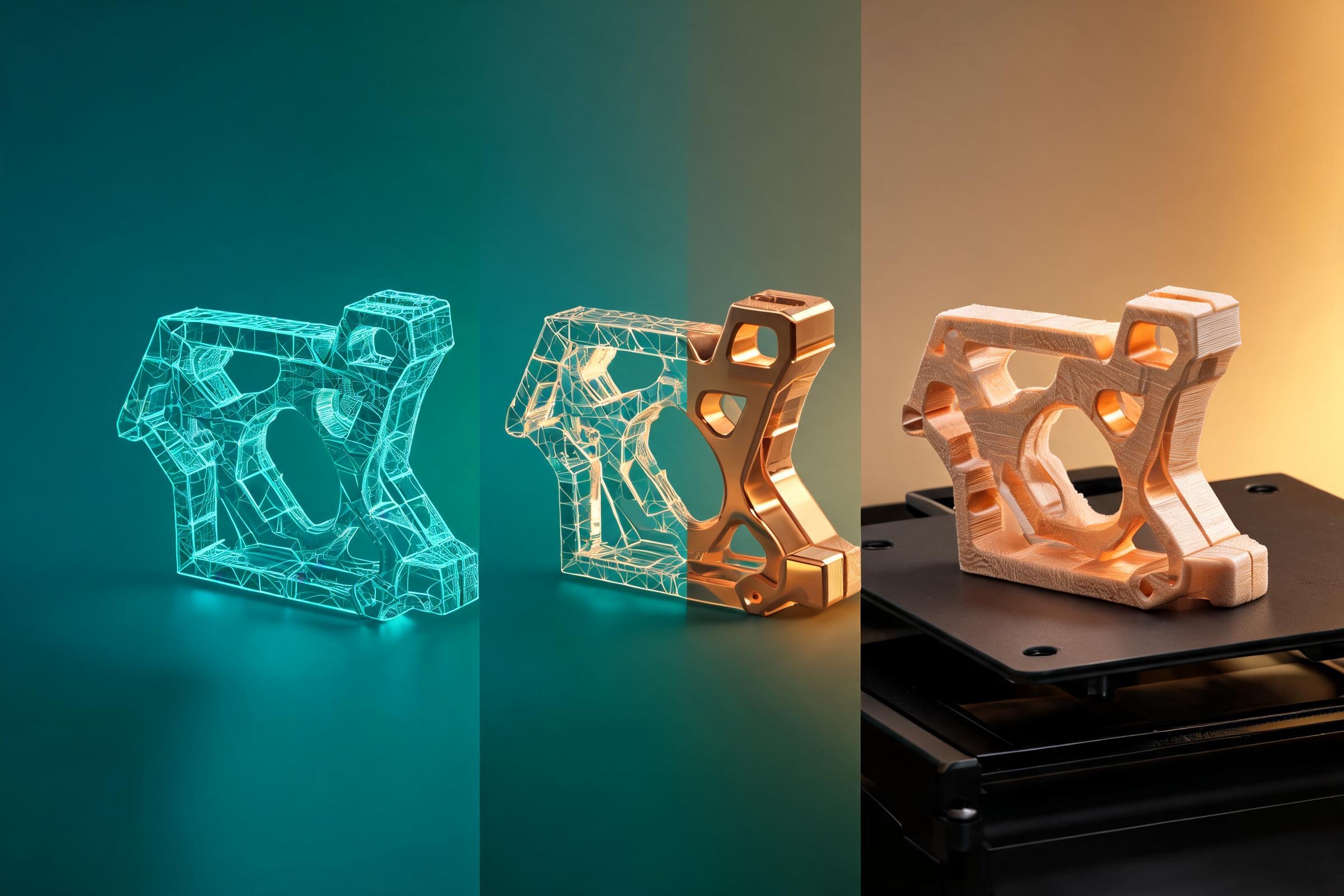
3D printing is a group of additive manufacturing processes that turns digital model data into a physical object, commonly by building material layer by layer. A model is prepared, oriented, sliced, and sent to a machine that deposits filament, cures resin, fuses powder, binds particles, or uses another process-specific method. The printed object usually needs removal, cleaning, support removal, curing, finishing, or inspection. “3D printing” describes a family of technologies, not one universal machine or material.
3D printing and additive manufacturing
In everyday use, 3D printing and additive manufacturing are often treated as synonyms. In industrial contexts, additive manufacturing is the broader standards-oriented term for creating parts from 3D model data by joining material, generally layer by layer, rather than removing material from a larger block. The label does not imply that every part is plastic, inexpensive, fast, strong, accurate, or ready to use immediately.
The contrast with subtractive manufacturing is useful but incomplete. Milling and turning remove material; forming reshapes it; casting fills a mold; additive processes build geometry selectively. Real production systems often combine methods. A metal additive part may be heat-treated and machined on critical faces. A polymer print may receive inserts, coatings, sanding, or assembly. The best process is selected from requirements, not from novelty.
3D printing is valuable when geometry, customization, iteration speed, low tooling volume, or distributed digital production outweigh process limitations. It can make internal channels, lightweight structures, patient-specific geometries, jigs, fixtures, patterns, prototypes, and end-use parts. It can also be a poor choice for a simple high-volume part that another process makes faster, more consistently, or at lower total cost.
The digital-to-physical chain
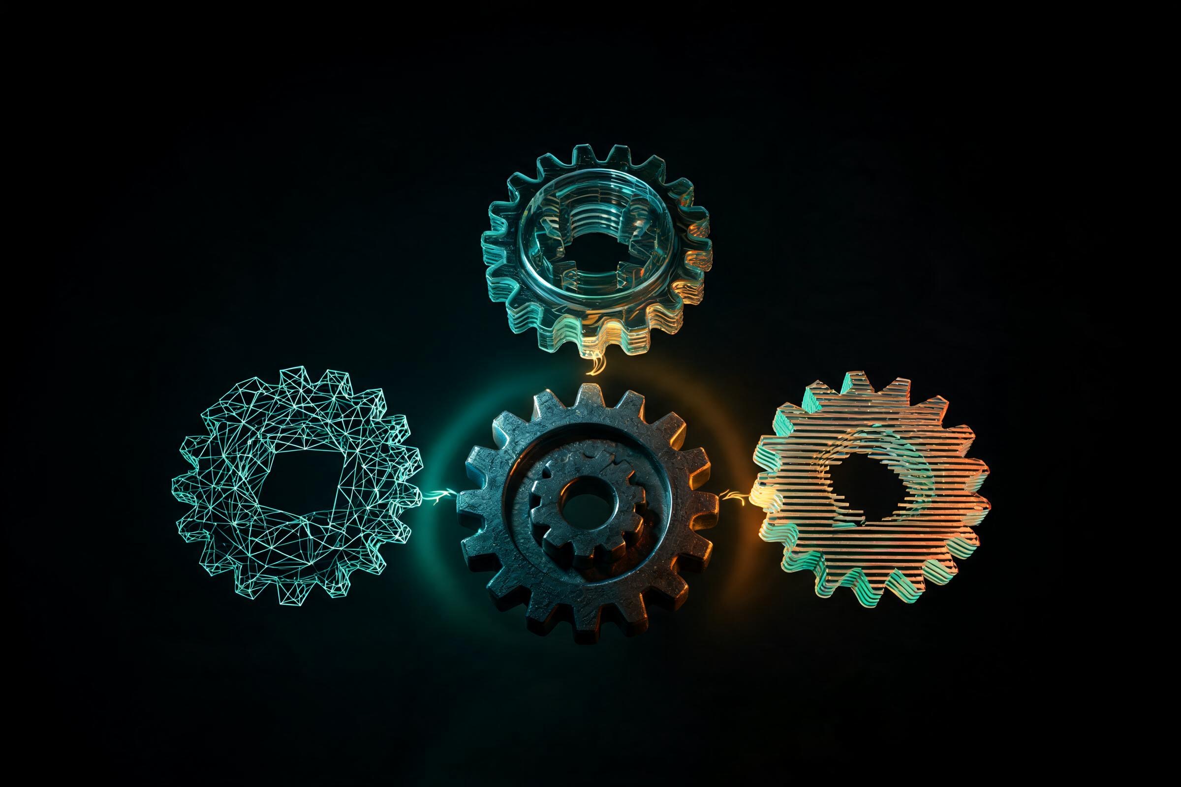
A printable object begins as data, but the data may come from CAD, polygon modeling, sculpting, scanning, procedural design, or AI-assisted generation. The source must be translated into a representation the preparation software understands. That translation can lose units, metadata, materials, parametric history, or topology. Keeping the editable master is therefore essential.
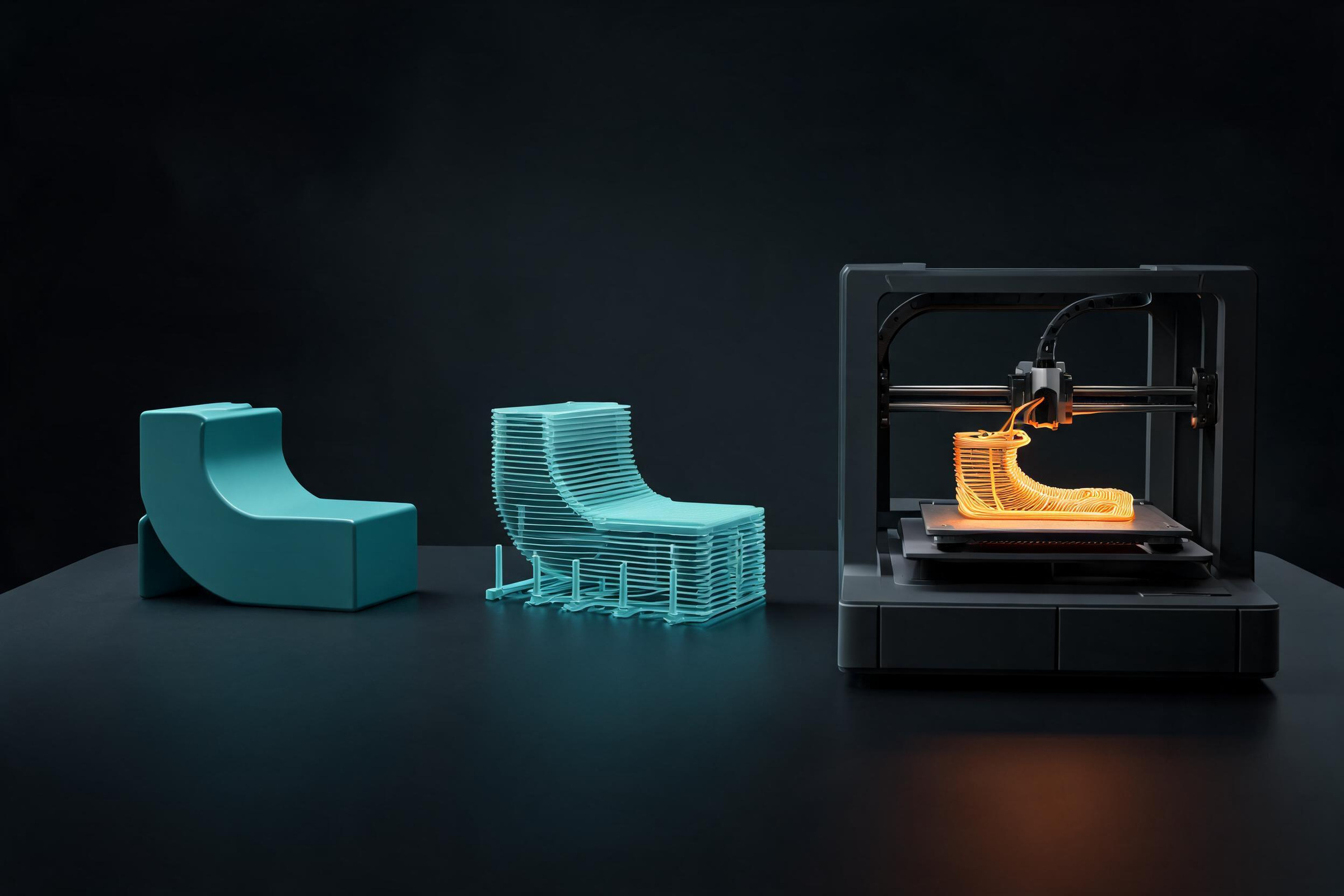
Preparation software or a slicer places the object in the build volume, applies process settings, creates supports when needed, and divides the geometry into layers or toolpaths. The machine follows those instructions while controlling motion, energy, material delivery, temperature, exposure, atmosphere, or other process variables. After the build, the part is removed and post-processed according to the technology.
Each transition can fail. A valid-looking mesh may contain holes or self-intersections. A correct solid can be oriented poorly. A suitable material can be wet, contaminated, expired, or processed outside its window. A completed build can be damaged during support removal. Digital success and physical success are related but not identical.
Major process families in plain English
This process-family guide compares the bonding mechanism, common feedstock, and main preparation concerns for each major additive-manufacturing route.

Material extrusion
- How material becomes a part: Material is pushed through a nozzle and placed along paths.
- Common material forms: Thermoplastic filament, pellets, and pastes.
- Typical considerations: Layer adhesion, warping, toolpath width, and support.
Vat photopolymerization
- How material becomes a part: Light selectively cures liquid photopolymer.
- Common material forms: Resin.
- Typical considerations: Washing, post-curing, support marks, and resin handling.
Powder bed fusion
- How material becomes a part: Energy fuses selected regions in a powder bed.
- Common material forms: Polymer or metal powder.
- Typical considerations: Powder handling, thermal control, and depowdering.
Binder jetting
- How material becomes a part: A liquid binder joins selected powder regions.
- Common material forms: Sand, metal, and ceramic powders.
- Typical considerations: Fragile green parts, curing, infiltration, or sintering.
Material jetting
- How material becomes a part: Droplets of build material are deposited and cured.
- Common material forms: Photopolymers or wax-like materials.
- Typical considerations: Support material, finish, and material behavior.
Directed energy deposition
- How material becomes a part: Material and focused energy create or repair features.
- Common material forms: Metal powder or wire.
- Typical considerations: Heat input, shielding, and machining allowance.
Sheet lamination
- How material becomes a part: Sheets are bonded and cut to shape.
- Common material forms: Paper, polymer, or metal sheet.
- Typical considerations: Bond quality, accessible geometry, and finishing.
This table is a map, not a purchasing guide. Machines within one family differ substantially. A desktop filament printer and an industrial extrusion system share a principle but not necessarily capability, control, material qualification, or acceptable use.
What 3D printing is used for
Prototyping remains a core use because a team can test form, fit, assembly, airflow, user interaction, or manufacturing assumptions before committing to expensive tooling. The key is to design the test around a decision rather than treating every print as a final replica.
Tooling and manufacturing aids include jigs, fixtures, inspection holders, drill guides, soft jaws, patterns, and assembly aids. These uses can be valuable even when the sold product is made conventionally, because the geometry is customized and volumes are low.
End-use parts are possible when the selected process, material, controls, and verification satisfy the requirement. Examples range from ducts and brackets to dental devices and aerospace components, but “printed” is not evidence of qualification. The application determines testing, documentation, and regulatory duties.
Education, art, accessibility, and research benefit from rapid physicalization of ideas, but rights and safety still apply. Downloaded or generated models may have license restrictions. Small parts can be choking hazards; resins, powders, fumes, heat, lasers, and moving machinery require appropriate controls.
Benefits and limits without hype
3D printing can reduce dedicated tooling for low-volume work, support complex geometry, allow mass customization, and shorten some design loops. It can consolidate assemblies or create internal structures that are difficult to machine. Digital files also make it possible to produce near the point of use, provided equipment, material, calibration, and quality controls are equivalent.
Limits include anisotropic properties, process variation, surface stair-stepping, supports, restricted build volume, material constraints, post-processing labor, and inspection difficulty. Cost per part may remain high at scale. A geometry that can be built may still be hard to clean, measure, repair, or certify. Sustainability claims also require a full comparison: failed prints, supports, energy, feedstock production, recycling, logistics, and avoided tooling all matter.
A responsible answer to “Can this be 3D printed?” is therefore “possibly, after requirements and process are matched.” The correct next questions are: What must the part do? What material behavior is required? Which surfaces are critical? How many are needed? What evidence will establish acceptance?
Glossary of essential 3D printing terms
- Additive manufacturing (AM): Making parts from 3D model data by joining material, generally layer by layer.
- Build plate: Surface or platform on which the part is built or attached.
- Build volume: Maximum machine workspace available for a build.
- CAD: Computer-aided design tools used to create controlled digital geometry and engineering intent.
- G-code: A common machine-instruction format in some workflows; not a universal format for every AM process.
- Layer height: Nominal vertical increment between deposited, cured, or fused layers; smaller is not automatically better overall.
- Mesh: A surface representation made from polygons, commonly triangles for STL.
- Overhang: Geometry extending without sufficient material beneath it for the selected process and orientation.
- Post-processing: Steps after the build, such as washing, curing, depowdering, support removal, heat treatment, machining, or finishing.
- Slicer: Software that converts prepared geometry and settings into layers, paths, exposures, or machine instructions.
- Support structure: Temporary geometry that stabilizes or anchors regions during a build and is later removed or separated.
- STL: A widely used triangulated surface format that usually lacks reliable unit and manufacturing-intent metadata.
- 3MF: A container format designed to carry richer manufacturing information than basic STL, subject to software support.
- Watertight/manifold mesh: Informal preparation terms for geometry that encloses a coherent volume without unintended boundary defects; this alone does not guarantee printability.
How to evaluate a first project
Choose a non-safety-critical object with a clear purpose. Confirm that you have the right to use the model. Inspect dimensions, orientation, wall thickness, supports, and material guidance. Run the slicer preview rather than relying on the shaded model. Start with a small calibration or partial print where failure would be inexpensive.
Document the file version, machine, material, settings, environment, and changes. Compare the result with the intended function and record what failed. If the object touches food, carries a load, operates near heat or electricity, contacts the body, or is used as a medical device, obtain application-specific expertise rather than extrapolating from a hobby print.
Continue the print-preparation workflow
Use the AI 3D printing model editor to move from a concept toward editable geometry. Before export, compare FBX, glTF, OBJ, and STL handoff choices, run mesh cleanup and repair, reduce unnecessarily dense geometry with the free 3D polygon reducer, and finish with the scale, slicing, and support checklist. These tools support preparation; they do not certify a part for a specific printer, material, load, or regulated use.
Sources and freshness
- ISO/ASTM 52900:2021 — Additive manufacturing terminology, edition published 2021; checked 2026-08-04 for the process definition and category vocabulary.
- NIST — Additive Manufacturing, checked 2026-08-04 for measurement, process control, and qualification context.
- U.S. Department of Energy — Additive Manufacturing, checked 2026-08-04 for manufacturing context and the layerwise-build explanation.
- U.S. FDA — 3D Printing of Medical Devices, checked 2026-08-04 for regulated-use boundaries.
A concise, citable summary is: 3D printing is a family of additive manufacturing processes that makes physical objects from digital model data, usually by building material layer by layer; the exact material, bonding method, accuracy, and post-processing depend on the selected process. Standards and vendor guidance change, so verify the current machine, material, and service-bureau documentation before committing a production part.
FAQs
Is 3D printing the same as additive manufacturing?
The terms overlap heavily. Additive manufacturing is the broader standards and industrial term, while 3D printing is common in public and desktop contexts. Both cover multiple process families, so name the specific technology when material behavior, capability, controls, or qualification requirements matter.
What are the main families of 3D-printing processes?
Major families include material extrusion, vat photopolymerization, powder bed fusion, binder jetting, material jetting, directed energy deposition, and sheet lamination. They differ in how material is delivered and bonded, which determines compatible feedstocks, support strategy, post-processing, safety controls, and practical applications.
What files are used in a 3D-printing workflow?
There is no single universal file. Geometry may arrive as STL, 3MF, OBJ, or another exchange format, while preparation software creates machine- and process-specific instructions. Preserve the editable source model and verify units, orientation, supports, materials, and settings during every handoff.
When is 3D printing a good manufacturing choice?
It is often useful for prototypes, customized geometry, complex internal features, low-volume tooling, jigs, fixtures, patterns, and qualified end-use parts. It may be a poor choice when a simple high-volume part can be molded, formed, cast, or machined more consistently at lower total cost.
What does a successful 3D print not prove?
A successful build does not by itself prove dimensional conformance, repeatability, strength, chemical compatibility, food safety, biocompatibility, regulatory compliance, or fitness for service. Acceptance requires requirements, a controlled process, appropriate inspection, and application-specific testing rather than visual appearance alone.